Introduction
This was a class project in which Nicholas Kramer was my lab partner.
In the wake of the power wall in computing and the industry migration to parallel systems, we developed a toy to aid in the education of the primary principles of parallel computing.
The conscious mind processes in serial. This is because human communication is inherently serial. Spoken words are formed one at a time and heard one at a time. Even as you try to understand this sentence, you read the words in a sequential manner. It is not surprising, then, that students have a much easier time understanding serial systems rather than parallel systems. Despite this, there is a growing need for students to be able to analyze and construct parallel systems.
In recent years, we have seen computer manufacturers hit a power wall, and consequently rendered incapable of increasing the speed of their processors. To continue to improve performance, parallelism has been embraced at an architectural and programmatic level. In addition to faster computing, there are some problems that lend themselves to a parallel rather than serial solution. For example, physical simulations, facial recognition, and learning systems all benefit greatly from parallelism. Designers of these systems need to understand parallelism at an intuitive level to reap the benefits.
We developed a toy that enables easy experimentation and exploration of parallel systems to build this intuition. And we thought that the proper vehicle for this exploration is the most common parallel system by far: the brain.
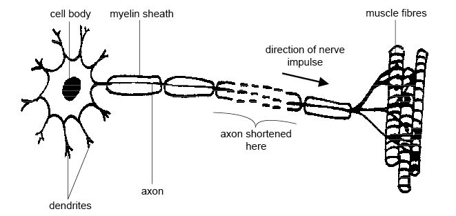
At a very basic level, the brain is a massive interconnect of many simple neurons. A neuron receives inputs from and provides outputs to other neurons. When the values of the neuron's inputs add up to the neurons threshold, it will fire and deliver a signal to all neurons connected to it downstream. Complex behavior can emerge even from very simple topologies. Five neurons can categorize the digits between zero and nine. Two neurons can serve as any two input logical gate.
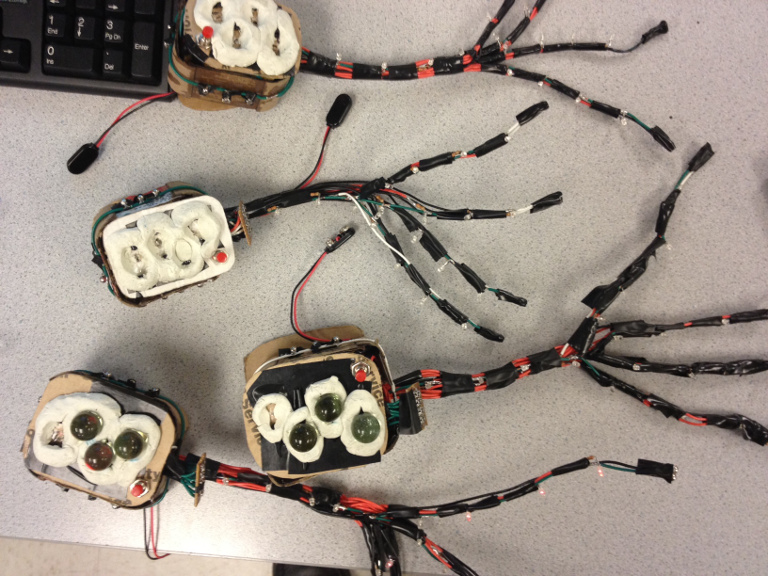
Our toy consists of several modular pieces that each act as a single neuron and can be assembled by the user. The neurons took much longer to manufacture than expected, so time constraint limited us to constructing four neurons for demonstration purposes. Should we take this toy to the market, each set would contain 10-20 neurons. We designed each neuron with two constraints in mind: First, it must be easy and intuitive to assemble networks of these neurons. Second, the activity of each neuron and the network as a whole needs to be easy to understand so the user can watch information flow through the network to gain insight.
In the spirit of making this toy an educational tool, we created each neuron module to mathematically resemble a perceptron and anatomically resemble a motor neuron. Mathematically, perceptron are very powerful tools for binary classification and dynamic systems, and function very similarly to the biological motor neurons described above. The inputs of each perceptron feed into a large head where all the computation happens, and the outputs to feed out of a narrow tail. This mimics the dendrite and axon structures in a motor neuron.
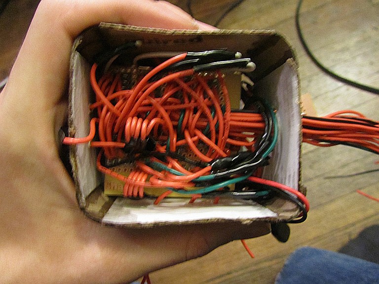
Each neuron is controlled by its own microcontroller. The Atmel Atmega16 microcontrollers are attractive candidates due to their minimal size, power consumption, and cost. Each neuron will has a method for connecting eight inputs, connecting four outputs, setting the threshold level, and setting the weights at the output. The casing consists of a custom built cardboard box in the shape of a motor neuron surrounding a box that houses the electronics.
Thresholds are controlled with a series of divots in the dendrite in which glass marbles can sit. When placing marbles on these divots, the microcontroller adjusts the threshold to correspond to the total number of threshold units the marbles are contributing. As action potential accumulates at the neuron's inputs, it displays how close it is to the threshold by illuminating the marbles via an LED underneath the divot. For example, if three marbles were placed on the dendrite, the neuron would need three units of action potential to fire. If the neuron has 2/3rds of what it needs to fire, two of the three marbles will be illuminated.
Weights (the multiplicative factor telling how important an output is) are be controlled via a potentiometer. Ideally, these would have been a slider potentiometers, but cost would have quickly become a factor as the number of neurons scales. The user is able to adjust the weight of each output while easily seeing how much action potential that output is providing.
Interconnects between the outputs in the axon of one neuron and the inputs in the dendrite of another neuron have to be very easy to connect and disconnect for quick reassembly. This can easily be done by having each output be a flexible wire with a small neodymium magnet at the end. These outputs magnetically stick to input pins consisting of corresponding magnets on the dendrite. This fulfills our goals of having easy to construct networks, while still strongly resembling the biological structure of the neuron. To view signals traveling through the pathway, each input corresponds to an LED that lights when it is receiving a signal. We also attached a buzzer to each neuron so it produces a tone as it fires. Such a system would provide audiovisual feedback, as well as increasing the urge to explore and discover aesthetically pleasing topologies.
We designed this toy to for unguided use. However, if we choose to market our toy, we would write an accompanying lesson plan for using our toy neurons as an educational tool to learn basic topologies of neural networks. In addition to enriching the user, these lessons could provide them with new and interesting ways to assemble the neurons.
High Level Design
Inspiration
As students, we have seen processors going from a single core to many cores, as well as experiencing trouble creating heavily multithreaded applications. We started wondering how we could make our tough journey toward understanding parallelism easier. From an early age, LEGOs have inspired us to achieve in engineering and Mindstorms had given us the mental tools to understand linear systems. However, there was no such toy for understanding parallel systems, so we set out to make one. We decided that the most natural parallel system is a neural network. A neuron is inherently modular and intuitive, yet when neural networks get big enough, they are also incomprehensible.
Theory of Perceptron Operation
As mentioned above, the model we are using for a neuron is the perceptron. A perceptron is a binary classifier that produces a 0 or 1 (not firing or firing) based on whether w*x+b>0. Both w and x are vectors and b is a scalar offset. The dot product of the input vector (x) and the weight vector (w) computes the amount of action potential a perceptron is receiving. If this dot product exceeds the value of b (normally a negative value) we say that the threshold has been reached and the neuron fires.
Let us consider a two input single output perceptron. Say we want it to fire under the AND situation (if and only if both of the inputs are 1). In the following picture, this situation is illustrated. Note that the region w*x+b>0 encompasses the region under which we want to return one, and excludes all the other values. The boundary is the line w*x+b=0. For the right values of w and b, a perceptron can be trained to linearly divide the plane into any two regions.
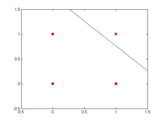
This perceptron was trained using a Matlab function I wrote (See Appendix E). X and Y are inputs, color is the output.
In a more complicated example, see the following Matlab plot. This scenario uses two perceptrons to divide the plane into four regions, classifying each type of input (red, blue, green, and black) into a unique output of the neural network.
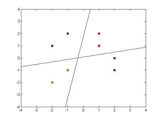
This perceptron was trained using a Matlab function I wrote (See Appendix E). X and Y are inputs, color is the output.
The Playflow
One of our originating requirements of this design was to easily watch data flow through the user created network. Each neuron in the system thus communicates with other neurons at a slow enough speed for the user to track the dataflow. Take the following network as a simple example topology a new user may play with.
Both of the neurons default to zero. Thus we need an external stimulus to start activity. This is in the form of a button on the top of the neuron that forces a fire. When the user applies this starter to one neuron, it will cause the neuron to fire. The LEDs in the neuron will light up to indicate firing. As the second neuron has reached its single threshold unit, the LED corresponding with that threshold marble will light up indicating the neuron has reached its threshold potential. In the next cycle, the first neuron will stop firing as it no longer has the starter forcing a fire. However, the second neuron will have gathered enough action potential during the previous cycle so it will fire and send action potential down its axon to the inputs of neuron one. The two neurons will thus oscillate, as that is the function of this neural network. Even with only two neurons, the system is interesting. It is easy to imagine the exciting networks that could arise with more.
Safety and Ethical considerations
As we are striving to design an entertaining and educational tool, we have several responsibilities. First, we need to make sure our design is safe. Our toy by its very nature has many exposed voltages and requires reassembly by the user. During design and construction we have paid special attention to making sure that the user can.t hurt themselves, their property, or our device with the exposed voltages. Exposed wires are taped down and in a custom enclosure. Interconnects have been built in a manner that repels the user hooking up voltages wrong.
Secondly, we have the responsibility to improve the publics understanding of parallel information flow and neural networks. At every design decision, we attempted to make our neurons more realistic and more intuitive to aid in the users acquisition of understanding. We attempted to make the prerequisite knowledge barrier as low as possible so the learning potential is available to everyone.
Lastly, we are accountable for preventing our project from spreading misconceptions. By taking the roles of educators we are accepting the burden of assuring the knowledge we impart is both accurate and unambiguous. We would be doing a disservice to the user's academic career should our toy mislead or teach using a model with erroneous assumptions. Because of this, we made sure to never trade ease of use for accuracy.
We believe we constructed a safe, intuitive, and accurate toy that would be accessible to a wide audience should we go into mass production.
(Note: Article Four of the IEEE Code of Ethics was obeyed by refusing to accept the bribery of extra points to finish early.)
Hardware Design
Programming using Dragon and Developing using Atmega16
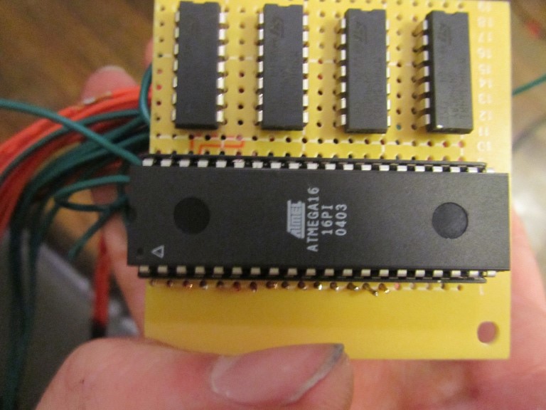
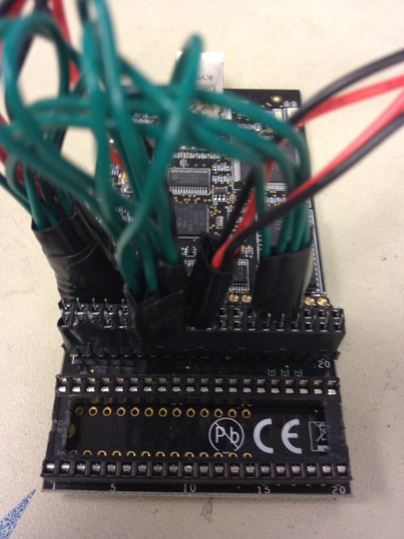
We were very fortunate to find an AVR Dragon programmer in the spare parts bin. This discovery has been extremely helpful in our workflow, allowing us to program, prototype, and power our design during the development phase. This was not without some setup, however. First, a 40 pin DIP socket was soldered to the EXPAND header for easy programming and removal of the Mega16. Next, we soldered a complete suite of custom headers to easily connect relevant ports to the EXPAND header as well as splicing power from the USB to power our development board.
After a semester of working with the Mega644, porting to the Mega16 was not a trivial task. The registers have slightly different names and are assigned to different bits. The timers also behave slightly differently. Finally, some functionality was completely missing from the Mega16. For example, some WGMs were missing and pin interrupts are completely nonexistent. This required us to be very careful about code reuse from previous assignments.
We chose to use the internal clock of the Mega16 that runs at 1MHz. This design decision was made to minimize the cost of an external clock and lower the power to make the battery of each neuron last longer. Our program does not require high speed or precision timing, so the lowered clock speed doesn't negatively impact us greatly.
Soldering and Board Layout
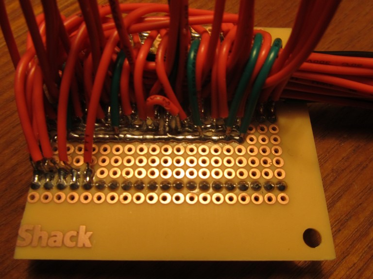
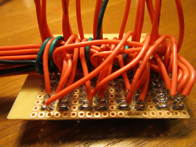
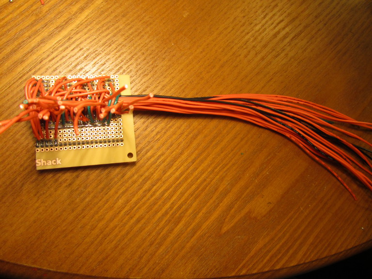
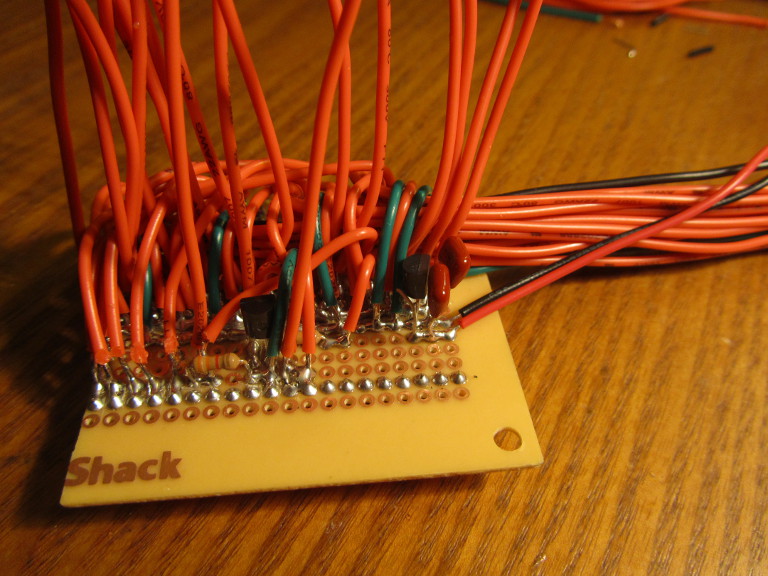
While there is no component in a single neuron is individually expensive, our project could have become pricy quickly by the fact that we made many identical units. Fortunately, we were able to mitigate this cost by scavenging parts from various past projects. Our solder boards were completely scavenged from boards we found and recycled. We desoldered the boards, sanded the contacts, and then cut them into 18 pins by 20 pins pieces. This was large enough to house a 40 pin DIP socket, four shift registers, and a few extra rows for connections.
This proved to be plenty of room, seeing as we are housing many of our components off of the solder board. Each of the 28 animation and status LEDs per neuron have their leads cut short and a resistor soldered to the positive terminal. Each of these are wrapped in electrical tape and floating along the axon.
Weights
Our method of changing weights has changed a lot from its original form. Our originating requirements were an easy and intuitive system. We originally intended to have an array of switches on each axon branch such that the set weight would be proportional to either the absolute number of switches down or some binary encoding of the switches down. Concept sketches showed this idea to be clunky and cumbersome and so was abandoned in favor of potentiometers.
Potentiometers, while slightly pricier, have the advantage of being intuitive and continuous. This means we can make an arbitrary number of weights limited only by the accuracy of the ADC.
The potentiometers were originally going to be placed on the base of each axon branch. Each potentiometer controls the weights of the corresponding axon. Each of the potentiometers is fed back to an ADC line of the Mega16 for conversion. Our latest design only uses four weight possibilities due to the results of playtesting, so extreme precision is not required.
In future designs, we could implement a much more attractive design. Embed a potentiometer toward the end of an axon branch. Glue a magnet (see section on connections) to the rotating part of the potentiometer. This lets the user rotate the connection between two neurons to set the weight.
Thresholds
Our design for thresholds was very volatile during development. We originally envisioned a series of switches in a ring on the dendrite. Threshold would be determined based on how many switches were closed. This design wasn't as intuitive as it might be, however, as it is difficult to mentally track the states of each switch.
We felt as though something the user could hold and feel would make the threshold units more symbolically significant. A marble is an easy to find and easy to understand object, so it made a lot of sense to have the dendrite sense how many marbles were placed on it, each marble representing a threshold unit. Marbles also solidly light up when a red LED is placed below them. We took advantage of this this fact to create a display to visualize what fraction of the total set threshold has been accumulated; if a quarter of the set threshold has been reached, a quarter of the marbles will glow red.
To sense whether a marble is present, we intended to put buttons at the bottom of divots in the dendrite housing so that a marble would press the button. We found this system to be finicky, as the button would toggle states if the neuron was bumped.
Having had success with light gates in the PID control lab, detecting marbles using a light gate seemed like a fruitful idea.
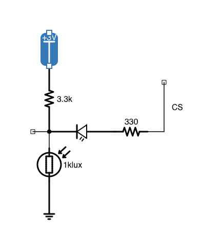
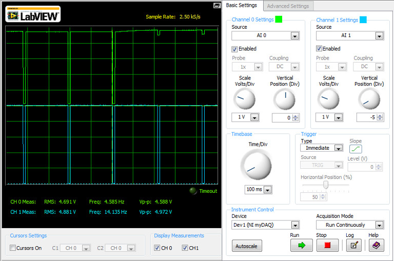
With the phototransistors and IR LEDs we chose to use in our light gate, a finger placed in the dendrite divots yielded a 4v voltage drop which is enough to toggle the state of a Mega16 input pin with no need for ADC or comparators. However, while flesh is a good IR absorber, the glass in marbles did not function as well.
Steel marbles were a viable possibility. These of course absorb IR light very well. But this would ruin the glowing marble visualization of action potential accumulation. We needed a clear coating that could be applied to the marbles to block infrared yet pass visible light.
In a moment of divine inspiration, nail polish as an IR filter was suggested. Preliminary research showed that nail polish does in fact filter infrared. We painted several clear coats onto a marble and tested this. While minor IR filtering did occur, the effect was not profound enough to be practical.
Glass marbles do not filter IR, however they reflect it very well. One design used Brewster's angle to cause reflection in a way such that the light from the emitter would miss the receiver if and only if a marble were placed in a divot.
This layer of complexity was avoided when we found a set of slightly opaque marbles. These would visibly light up when a red LED was shone onto it, but would block infrared enough to cause a pin change on the Mega16.
Animation and Firing
Animating the firing of a neuron with myriad LEDs is essential for our design to make the flow of data more visual and intuitive was very important to our desire to use the neurons as an educational toy. Such an animation involves action potential (light) flowing from the dendrite (where action potential was collected from other neutrons) down the axon and out each axon branch (where the action potential will be output).
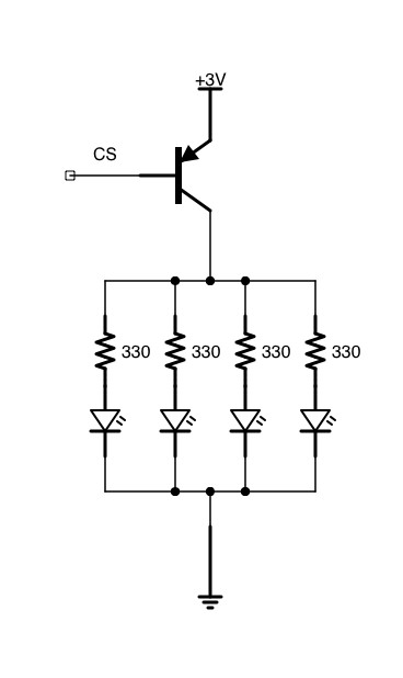
From an idealistic perspective, the denser the lights, the better. However due to budgetary, practical, and time limitations, we decided four LEDs per axon and four per branch was sufficient. Every time the neuron fires, a light trail will flow down the axon and then into each of the four branches. A very convenient way to do this is with the use of shift registers.
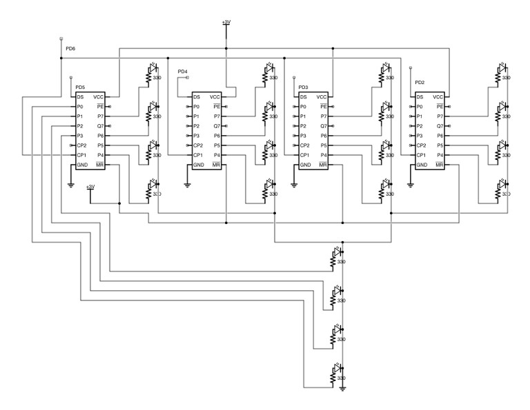
We found serial input, eight bit parallel output shift registers which is ideal for our application. We make use of four shift registers per neuron. One of these shift registers uses the lower four bits for the axon LEDs (see hardware schematic). All four shift registers have the upper four bits connected to the axon branch they are associated with. The 12 bits not mentioned are left unconnected.
Another advantage of using such an animation system is it allows for visualization of the weight of each branch as of the previous fire. To understand how this is so, briefly consider our algorithm for animation.
Every time the neuron fires, the clock controlling all four shift registers will output twelve rising edges. As our shift registers are positive edge triggered, this equates to twelve shifts. For the first four cycles, we preload each shift register with four ones to provide a solid flow of light. At this point, the four axon LEDs will be illuminated. During the next four cycles, the weight will determine how many ones are shifted into each shift register. For example, if the weight on branch 0 is half and the weight on branch 1 is max, there will be two ones shifted into branch 0 and four into branch 1. At this point, the preloaded ones will be illuminating the LEDs on each branch and the weights will be in the disconnected bits. To finish the animation, we shift four more times. The animation ends here, and so the weights which are now lighting up the appropriate number of LEDs in each branch stay until next time the neuron fire.
Inputs
Using shift registers for animations has the added advantage of making the acquisition of inputs easy. Consider a single input line, connected to the fourth pin of the shift register (the one before four LEDs are connected). Note in the algorithm above that all ones that are transmitted are adjacent. Thus, once the neuron this input line is connected to fires, the line will go high for a set amount of time. We can measure this time and, knowing the frequency of animation, calculate how many ones were sent when that output fired. Remember that this number is the weight plus a constant four. Subtracting away a constant four per fire, you can determine when each attached neuron fires and the weight of that fire.
Accumulating action potential is then simply a matter of adding the weights of each input received, and firing if the inputs surpass a certain threshold.
Interconnects
If our toy is difficult to change configurations, the user's attention span will be shortened. The ability to quickly assemble structures is the reason toys such as LEGOs are so popular. Solid, fast, and removable connections are thus essential for the success of our toy. (Each interconnect must also provide two wire connections, namely ground and signal. For information on how this signal functions, please see the section on inputs. ) Requiring the user to assemble the device themselves raises safety concerns, so it is important to design the connections in such a way that it is difficult to short the device.
To alleviate safety concerns, our final design utilizes two polarized magnets attached to each output signal wire and the opposite poles in corresponding input wires. This would cause the input to snap into place and oppose a short. See the illustration for details.
Polarized block magnets proved pricier than expected, and so we came up with a design that uses half as many magnets. Our second design utilized a single magnet in the center of a triangular plug. Signal wires would connect at two corners of the magnet. There is no way to rotate this plug such that the signal wires connect in the reverse way. At least one wire will be disconnected unless they are both connected correctly.
We found large quantities of ball magnets, so we went with the design the less efficient design to make manufacturing easier.
That design, however, prohibits us from freely rotating the connection to adjust weights (see section on future directions of setting weights) as it lacks radial symmetry. Future designs could rely on a makeshift coaxial cable. The signal wire will be connected via two flush washers. The ground wire is connected through a ball magnet in the center of the washer. A small depression in the input as well as the pull between the magnets will make the connecter snap into place. This design also allows for rotation of the connection to adjust the weight potentiometers.
| Pin out: | PORTA | PORTB | PORTC | PORTD |
|---|---|---|---|---|
| 0 | Weight 0 | Input 0 | Threshold 1 | Reserved/Serial |
| 1 | Weight 1 | Input 1 | Threshold 2 | Reserved/Serial |
| 2 | Weight 2 | Input 2 | Threshold 3 | Shift Reg in 3 |
| 3 | Weight 3 | Input 3 | Threshold 4 | Shift Reg in 2 |
| 4 | Chip Select | Input 4 | N.C. | Shift Reg in 1 |
| 5 | Button Fire | Input 5 | N.C. | Shift Reg in 0 |
| 6 | N.C. | Input 6 | N.C. | Shift clock |
| 7 | N.C | Input 7 | N.C | Buzzer |
Results
Neurons were more difficult to manufacture than expected. Despite this, we made several functional neurons that fulfilled our originating requirements.
The solder boards were crowded and clunky at first, but after soldering together a few failed practice neurons, we were able to perfect an efficient layout that was easy to work with.
Our threshold marbles worked very well with little failure. Marbles were a intuitive system that enabled easy adjustment and visualization. The light gate design has enough voltage swing that pin changes were caused with no issues.
Animations worked better than expected. When a neuron fires, it prettily shows the action potential flowing. The LED chains were, while monotonous, not difficult to assemble. Controlling the animation with shift registers minimized the number of pins needed to drive the LEDs and simplified programming greatly.
The shift registers proved very helpful in neuron communications. Feeding shift register output three into the corrosponing axon branch output let the animations serve as data transfer.
The potentiometers we ordered were much smaller and more difficult to work with than expected. They were cheap which enabled us to keep each neuron's cost low (important were we to actually sell the neurons as educational tools), but difficult to solder and turn. Many of the potentiometers had a lifespan of a fixed number of turns, and so became useless at a stage too late in the game to change anything. Were we to continue development, we would likely change to a different potentiometer either a slide potentiometer on top of each branch or an internal potentiometer as described in Hardware Design.
Interconnects had mixed success. Some of the connections were weaker than desired, and once they were soldered on they became difficult to replace without redoing the housing. There is very little room for error. When we figured out an efficient workflow, we were able to create stronger and more efficient connections. Were we given the time to solder more interconnections from scratch, they would be much more solid and consistent. Despite this, the interconnections served their purpose and allowed dataflow.
We may be biased being designers of the neurons, but having played with the neurons we feel they are enjoyable and have the potential to be educational.
Progress Compared To Expectations
Our project was very ambitious. We foresaw not having enough time to complete all of the bells and whistles, and so we wanted to complete as much as possible while providing potential designs for expansion. We thus broke our project into 13 tasks that would have to be completed before we could publically release our toy. We made substantial progress during our allotted time, while paving the way for future expansion. While design and programming went very smoothly during the first three weeks, we did not foresee the massive time requirement (greater than 100 hours) that went into manufacturing. Considering this obstacle, we are very proud of the progress we made.
Below is our list of goals from our proposal updated with commentary on our progress.
- A single perceptron programmed on a Mega 16
- Programming and testing of a single perceptron was completed by the middle of week two. This complete.
- Hardware interface to the perceptron (adjusting parameters/displaying outputs)
- We completed and tested all proposed hardware interface and are pleased with the results. If we were to polish our design for the market, we would swap out the snub potentiometers for slide potentiometers, as well as use more diffusive LEDs to increase viewing angle.
- Communication between two neurons
- We have communication between neurons working.
- Several neurons (~4)
- Our efforts yielded four neurons. Wise associates advised us periodically to limit ourselves to four neurons instead of trying for ten. Despite amble pride, hard work, and stubbornness, we wound up taking this advice.
- User testing to adjust parameters and make neuron units more user friendly
- Peers (including friends and roommates) were consulted constantly throughout design to assure the design was intuitive. Despite discussion of the interface, enough neurons were not completed early on to do full user testing.
- Housing for the neurons including embedded interface
- A preliminary housing was completed. We feel that it suffices for our purposes. If we pursue development, we would create a silicone mold for an even nicer enclosure.
- Many neurons (~10)
- Time constraints prevented completion of ten neurons. In retrospect, it was a practically impossible and unreasonable goal.
- Lesson plans or guided exploration of neural networks using our several neurons
- Lesson plans were unfortunately not written. We look forward to doing this after classes end.
- Serial interface to computer using SPI to provide complex control over inputs
- We already have SPI communication coded for another board. However, there is no software or hardware support in our current design for SPI. This was cut as a nonessential component. A marketable design would definitely contain this feature.
- Software interface for computer
- This was made impossible by progress on 9. We did, however, experiment with interfacing software called ControllerMate and think that this would be a very viable solution. We interfaced many serial streams (including wireless streams from game controllers and phones) with our computer. It would be a simple extension to interface with a neuron.
- Input peripherals using software interface (such as a camera or small button matrix)
- This was made impossible by progress on 10
- Completely self contained neurons via inductive charging of rechargeable batteries
- Inducting charging is a non-necessary feature even for a commercial version of our project.
- Self guided learning for neurons (optional setting)
- Matlab scripts of learning algorithms were coded and explored. See Appendix E. Due to an insufficient serial input system, this code was never ported to the Mega16.
Future Directions
As alluded to above, we think there is potential market success for a neuron toy on the market. There is definitely a demographic that would be interested in such a toy; the oohs and aahs we received when a neuron chain first fired in the lab during manufacturing as a testament to the allure of controlling information flow.
Before our design goes into the hands of the public, we would need to make a few changes and optimizations. First, we would develop a smooth, flexible, silicone mold to encompass the electronic components and serve as a housing. Next, we would change the interconnects to our coaxial design. This would allow for stronger attachments, easier connections, and radially symmetric plugs. It would also enable us to embed weights in the connections as described in hardware design. Finally, we would choose LEDs which are more diffusive to provide a wider viewing angle.
Conclusion
While we regret not having time to produce more neurons, we are very pleased with our progress. Our neurons have fast and easy to change connections. Weights are able to be updated with minimal effort and will change the strength of an output. Thresholds are very intuitive and easy to set and the marbles glow when a threshold unit is reached. The neurons are capable of communicating with each other and fill with action potential based on the strengths of the weights. Firing occurs when the set threshold is reached, or when the button is pressed. When a neuron does fire, a very satisfying animation flows down the axon into the connected neurons.
This is substantial success and fulfills our project as initially imagined. Considering the huge time overhead that occurred with manufacturing, we believe we put the effort and passion into our project that it deserved, and were rewarded with an inexpensive and fun toy. Once our schedules are freed from the chaos of the end of the semester, we believe the work on our toy developed a solid foundation to turn our project into a useful, publically distributed pedagogical tool.
Appendix A: Program Listing
ISR
The ISR accumulates input on each axon by counting the time in which each input in INPUTPIN is high. Once an input has been high for TIMEBETWEENANIMATIONS (this value is consistent between neurons) the ISR adds 1 to the lower four bits of inputCount (the value of the input signal) and resets the counter, the upper 12 bits of input. When a pin in the input goes low, the input it has accumulated in the bottom four bits of inputCount is added to the value that the neuron holds and the corresponding index in inputCount is reset. this allows for the neuron to accumulate the input from various axons/inputs into a single value so that it can be compared to a threshold. ISR also sets flags for animation and firing once every animation interval. This allows the animation to be played at a visible rate and coherently with succeeding neurons. Lastly, the ISR removes pause flags after pause timers have timed out.
detectNumThresholds()
This function reads PORTC to detect whether or not there is a threshold marble in place (active high) at each pin and sums the ones to get the total threshold value. THRESHDDR must be set to 0 in order to read from the phototransistors because the hardware for displaying the threshold units is also used for reading.
detectWeights()
Uses the Analog to Digital converter to read the voltage across each potentiometer.
Appendix B: Parts List
Note that the following listing is per neuron.| quantity | part # | part | price ($) per part | total price ($) |
|---|---|---|---|---|
| 4 | 497-1789-5-ND | IC REGISTER 8BIT SIPO 14-DID | 0.16 | 0.64 |
| 1 | 3M5471-ND | SOCKET IC OPEN FRAME 40POS .6" | 0.45 | 0.45 |
| 4 | MARBLES | Preowned | 0 | |
| 12 | MAGNETS | Preowned | 0 | |
| 1 | MCP1702-3002E/TO | 3V VOLTAGE REGULATOR | 0.10 | 0.1 |
| 1 | BUZZER | Free | 0 | |
| 1 | 9V BATTERY | Preowned | 0 | |
| 1 | BUTTON | Free | 0 | |
| 1 | ATMEGA16 | Free | 0 | |
| 28 | CF14JT330RCT-ND | 330 OHM RESISTORS | 0.008 | 0.224 |
| 5 | CF14JT3K30CT-ND | 3.3K OHM RESISTORS | 0.008 | 0.04 |
| 4 | TC33X-103EDKR-ND | TRIMMER 10K OHM .1 SMD | 0.329 | 1.316 |
| 24 | WP710A10EC | 3MM RED LED | 0.07 | 1.68 |
| 4 | WP3DP3BT | 3MM PHOTOTRANSISTOR | 0.14 | 0.56 |
| 4 | WP3A10F3BT | 3MM INFRARED EMITTER | 0.07 | 0.28 |
| 1 | SOLDER BOARD | 0.66 | .66 | |
| 1 | EPOXY | Preowned | 0 | |
| 1 | CARDBOARD | Scavenged | 0 |
The total cost of a single neuron is $5.94. Considering there is not a similar product on the market, this is competitive pricing for what is offered. A starter set of seven neurons could be marketed for $40-45.
References
8 Bit SIPO Shift Registerhttp://www.datasheetarchive.com/dl/Datasheets-112/DSAP0051233.pdf
3MM IR LED:
http://www.datasheetarchive.com/ThumbnailsIndexer/Datasheets-SW12/tnDSASW00220046.jpg
3MM IR Phototransistor
http://pdf1.alldatasheet.com/datasheet-pdf/view/233333/KINGBRIGHT/WP3DP3BT.html
ATmega16: 8-bit Microcontroller with 16K Bytes In-System Programmable Flash
http://www.atmel.com/Images/doc2466.pdf